1, The pre-deformation design is the key
About auto air & water tank product plastic mold, the quality controlling of design and manufacturing are more difficult than normal type, as this type parts normally been molded by the material PA6 (PA66) + GF (30-35%) compound, and this kind of material is easy to get the deformation during the molding process, and corresponding product size are easy be out of tolerance. Therefore, familiar with its deformation regularity, then to do the pre-deformation design based on experience and CAE analysis result in the early design process has become the key to the success of mold manufacturing.
Enuo mold team has more than 10 years’ experience on pre-deformation mold making, and have served Valeo, Mahle-behr, Delphi and other world-renowned auto parts customers. Here we briefly introduce our experience on auto air & water tank mold making. For sure, different companies have different practices, if dear reader have different views, also warmly welcome to communicate with us.
2, Analyzing the parts drawings, clarify the key areas of the product and size
To understand important areas of the product and associated key sizes are always the first step when customers’ product drawings arrived, then pay more attention on those importance, such as product “End surface” (“End surface” was required most strictly straightness, flatness and form size tolerance, and other parts of the product dimension will follow their changing),”Tube orifice” area (the dimension of “tube orifice” is also very important, usually the positioning, cylindrical and dimensional tolerances are required)and product “Boss” and “U-shape” ribs etc., they are shown on below:

For new mold, do pre-deformation on the product (doing the “material compensation” on the opposite direction of estimated deformation in advance according to experience and CAE analysis, propose to make them correct after the actual deformation acted). After the mold trial, doing some small modification based on the actual deformation of the product molding, to correct the plastic geometry, shape and position and so on.
3, Drawing the products.
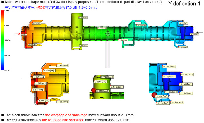
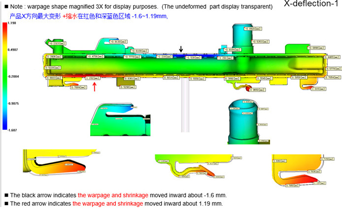
To facilitate the future mold optimizing, drawing a new 3D product data by ourselves according to customer’s product is necessary (important parameters should be retained). Determining the products deformation value, combined with mold flow analysis and experience to modify the product data, below you can see the experienced deformation trends:


Here, some tips are glad to be shared during the redrawing process, such as: always start at drawing the “Base end surface” area, according to the deformation value to draw straightness, flatness curve at the edge of product, refer to those curves to “Stretch”(UG command) straightness surface. Flatness surfaces are done with the “Border” (UG command). This step is important, to facilitate future changes, draw the curve first, do not “stretch” (UG command) surface directly, then using the deformation surface of straightness get the product shape by “Offset” (UG command). To avoid changing too many mold parts during the following mold optimizing, doing the plastic material cutting at the product “Base end surface” area, then recover them in T1-T3 modification based on the actual product deformation (plus plastic).
Tips paybe useful:
1. Do not copy customer products profile surface as far as possible, try to draw them by yourselves. So that,for the following mold modification are easy to be changed, including wall thickness. if the shapes are copy from customer product then after multiple modification,3D data will get the distortion.
2. In the process of drawing, as much as possible to check customer’s 2/3D product data to prevent they are different.
4,The possible deformation trend about product important part
1,The deformation of product “Base end surface”
As far as possible to do reducing action on the plastic material at the begining, it can avoid redoing the mold parts as far as possible. The red line below shows the product estimated deformation trend. please note the “Boss” or “U-shaped” ribs or related material should be moved with the “Base end surface” together(Some of the material under the boss moves down 0.5mm, then the “Boss” shuld also go down 0.5), and then draw others. It is recommended to use the “surface” (UG command) to draw them.


2,The product deformation of “Tube orifice”
The “R” radius shape at the root of the tube should be exactly same as customer product data, as this “R” radius affects the strength of the important area of the product. For normal circumstances, the round tube should be reduced plastic by side first,then change the value according to the actual deformation, for larger tube, the tube shape maybe designed as oval shape in advance.

3, the product “U” shape plastic bit deformation
“U-shape” plastic also need to do about 2-3 degrees deformation,the middle area of the “U -shape” ribs should do the material cutting by side also(picture 1). After all the products have been drawn well and then design the “R” radius(also for facilitating the changing, sometimes “R” radius rebuilding will fail or long time spent), if some geometrys in customer 3D data did not chamfered, we can chamfer them if they are not affect the parts assembly (most customers prefer the sharp shape be chamfered with “R” radius). In addition, some prominent geometry on the product main body are big , this type of product deformation should pay more attention on parallelism and perpendicularity (picture 2).

5, Conclusion
Above are our own experience on design the auto air & water tank-”easily deformation” product mold. completing this step good, i think half success of such molds manufacture would been got, then where is other half? please see the next section of this article “Do you know how to make pre-deformation mold?-manufacture section” next week.
Ok, dear readers. many thanks for your time to read here.looking forward to see you on next section!
Post time: Jul-27-2020


